|
FlashAdapter
 non thumb
Warnings and design notes
Basically you should not build this unless you could have created it yourself.Remember that this circuit is designed to protect your camera from "deadly"(at least to the camera) voltages/currents. This also implies that if this design has any flaws or if you screw up while building it you will destroy your camera! As usual I can't be held liable if you kill yourself, your camera, somehow manage to build your adapter smaller that its Schwarzschild radius or in any other event. First of all I don't know the exact specifications of "the PC Flash terminal", in some/all? cameras in the old days they were just switches that closed when the flash needed to fire. The following assumptions regarding modern PC flash terminals were used: They are open collector outputs (perhaps an IC output or if we are really lucky a smallsignal transistor) . They can only sink small amounts of current (in the mA range, most likely below 10mA) . They can only withstand logic level voltages on there terminal (most likely around 5V). Keep in mind that this is not a specification I have read somewhere and might be totally wrong. I chose opto-isolation in favor of over-voltage protection as I consider it to be safer for my camera. However opto-isolation do have a drawback, it requires an external power source. If the camera output is't open collector it may "charge" the battery this is slightly BAD. You may consider testing your output using a multimeter. The 47Ohm R1 gives rise to a relative large current through the opto-coupler led, this serves two purposes: Primary it should allow the usage of an 2.4V battery (2x Ni-MH or 2x Ni-Cd cells) even though they are less that ideal due to there large self discharge. Secondly it helps turn-on times of the opto-coupler. The MOC 3052 interesting parameters are: Turn on time of approx 11 us, isolation voltage of 7500V ac, the output stage can withstand 600V, 1A peak. R3 was originally intended to be a 1k Ohm, I did however not have one athand so I used a 1.8k Ohm instead. Higher means less load on the camera it however also requires a larger current gain of Q1. Eventually it will also reach a high enough value so that the voltagedivider made up of the pull-up R2 and R3 will not be able to go low enough to turn on Q1. When connecting the circuit to the camera use the correct polarity (locate it in your camera manual). Best case scenario for reversed polarity is that the flash just won't fire, worst case the camera may get damaged by the -3V it sees on its flash terminal. I don't know just how likely the worst case scenario is, but I always try to avoid subjecting ICs/black-boxes to voltages outside there power supply voltages. Better safe than black, fuzzy, without magic-smoke and sorry. Schematic
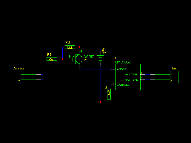 Here is the schematic in a tar.gz archive it is made using gschem. PCB
Sure here is the PCB layout.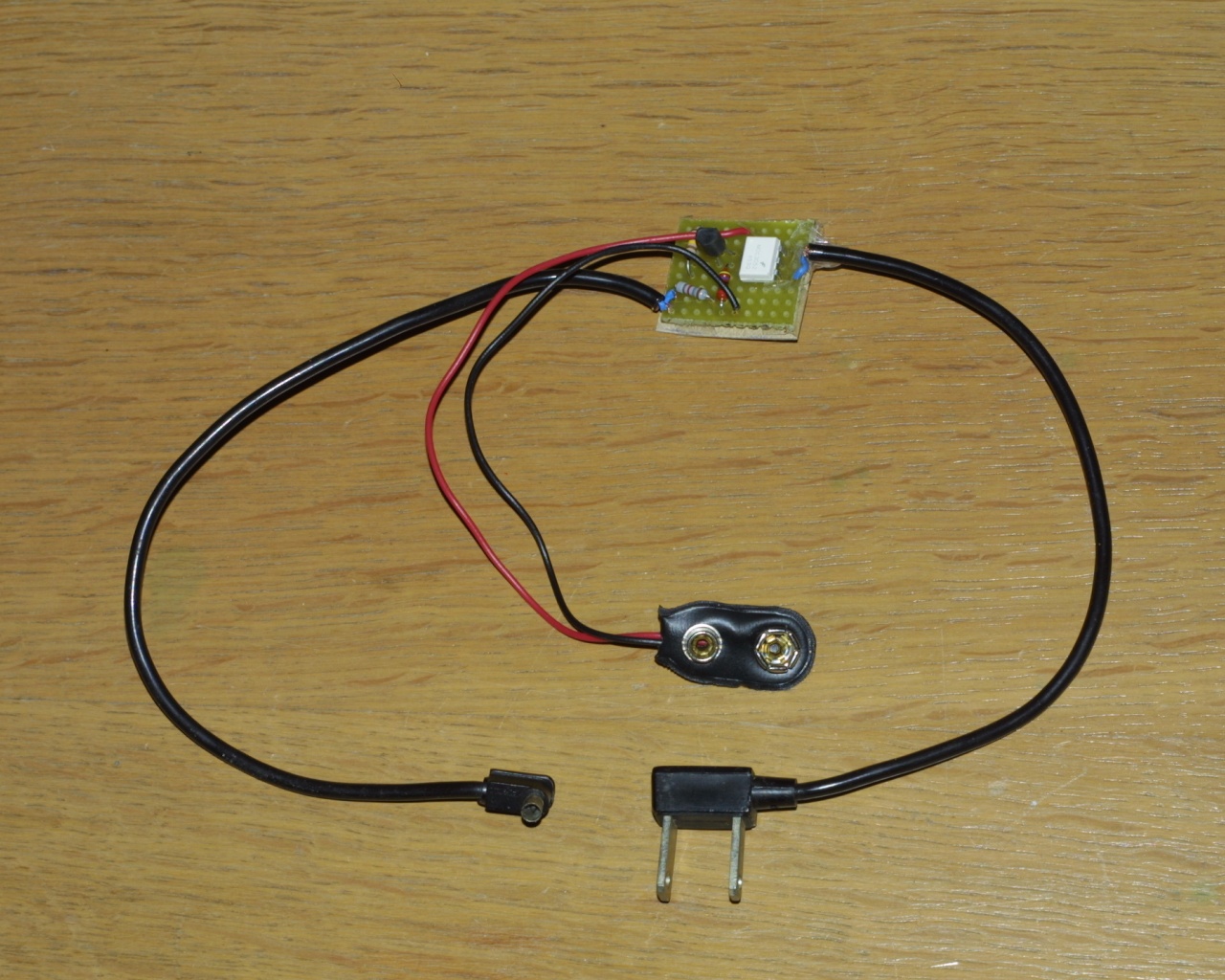 Oops I forgot I'm lazy so I just soldered the components on a tiny piece of prototyping board. I actually considered making a PCB as I hate to solder all those wires on the back of the prototype board. Still need to mount it in the nice enclosure with a belt strap that I bought for it. Also some extensions to the cables would be nice. PCB layout
Did I mention I'm a lazy bastard, of course I had to go ahead and use the adapter without mounting it inside the case.
As a result I ended up dropping the battery just once to often, resulting in one of the thin battery cords breaking.I then decided to make a proper PCB instead of just soldering the wire back on. The PCB layout should be easy to produce as it is single sided and uses wide copper tracks and clearances. 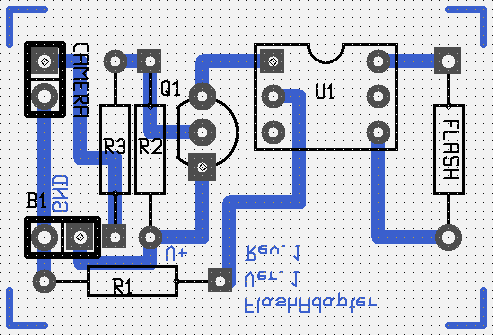 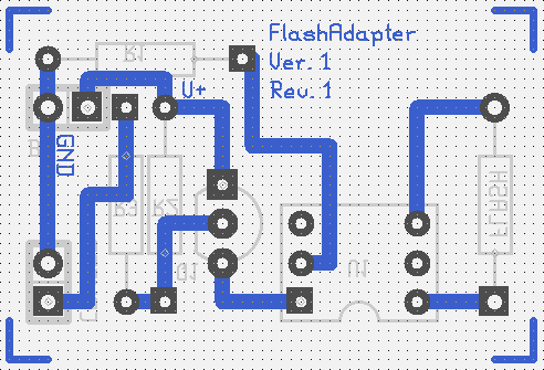 Here is the PCB as PS and as PDF and finally as a pcb file Please note I haven't etched the PCB yet so I can't say for sure that it works. pcb says that the layout is complete and has no shorted nets, but that is it. Test pictures
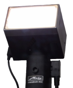
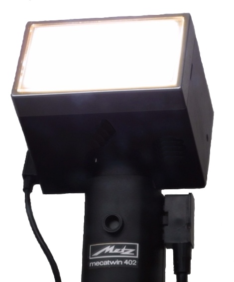
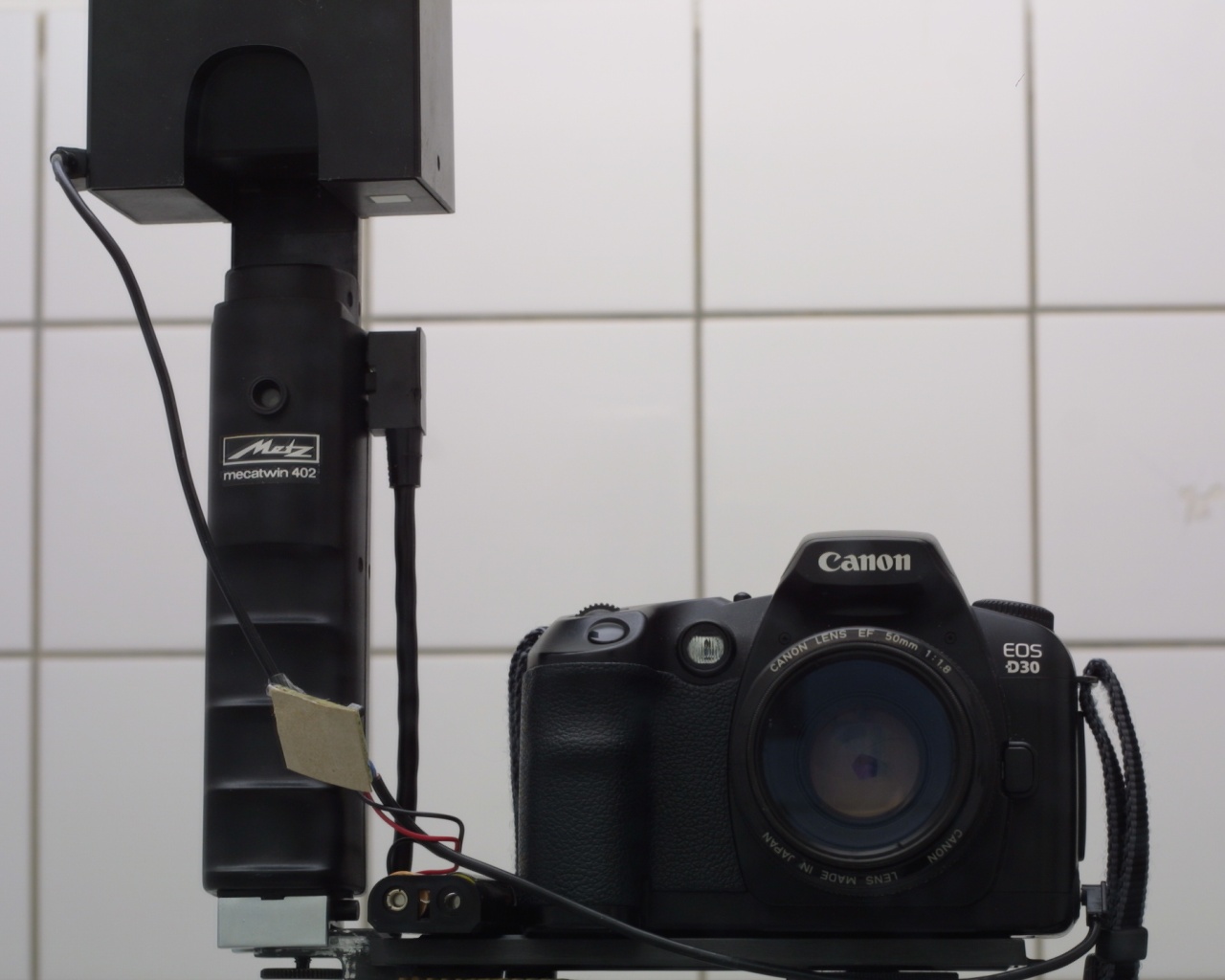 Flash bouncing works just fine, those old flashes may not be using TTL measurements but they work. 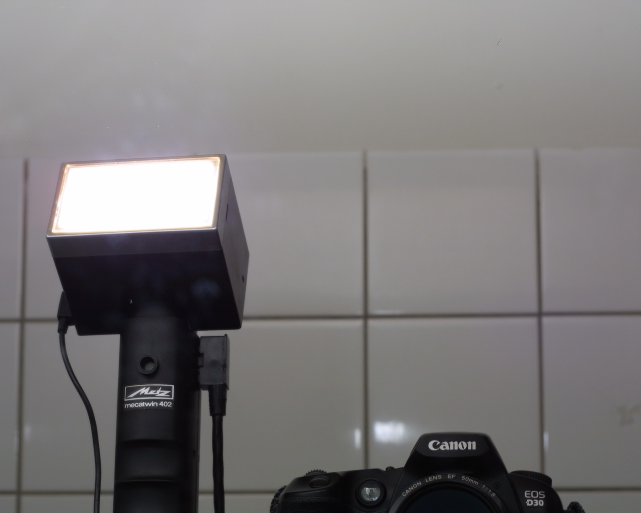 Another shot to show the flash firing more clearly. |
|
